


5Pcs MAX7219 Dot Matrix Module Microcontroller LED Module Display Module MAX7219 DIY Kit
187

 Direct purchase from the factory
Idaniloju sisan

 Ẹbun ọfẹ
 Ilana gbigbe
 Ilana pada
Ẹbun Ọfẹ
Kaabọ si Roymall, oju opo wẹ ẹbun rẹ. A dupẹ lọwọ rẹ, a si pese ẹbun ọfẹ pẹlu eyikeyi rira. Ṣetan lati ṣawari akojo wa? Yẹra ni koko wa, fi aṣẹ rẹ sii, ki o si gba ẹbun ọfẹ rẹ.Ilana Gbigbe
A nṣe awọn aṣẹ laarin ọjọ 2.Gbigbe deede jẹ ọjọ 5-7.Akoko gbigbe le yatọ da lori ibudo.1. Ilana Pada
A gba nikan awọn nkan ti a ra lati roymall.com. Awọn ẹbun ọfẹ ko le pada. Nkan gbọdọ jẹ ailohunsi ati ni apoti atilẹba.A nṣe awọn pada laarin ọjọ 3-5 lẹhin gbigba.Awọn nkan aṣa ko le pada.Kan si wa: service@roymall.com tabi Whatsapp: +86193598494712.Ilana Isanwo
Iwọ yoo gba isanwo lẹhin gbigba nkan. A ko san owo gbigbe pada.Kan si wa: service@roymall.com tabi Whatsapp: +8619359849471
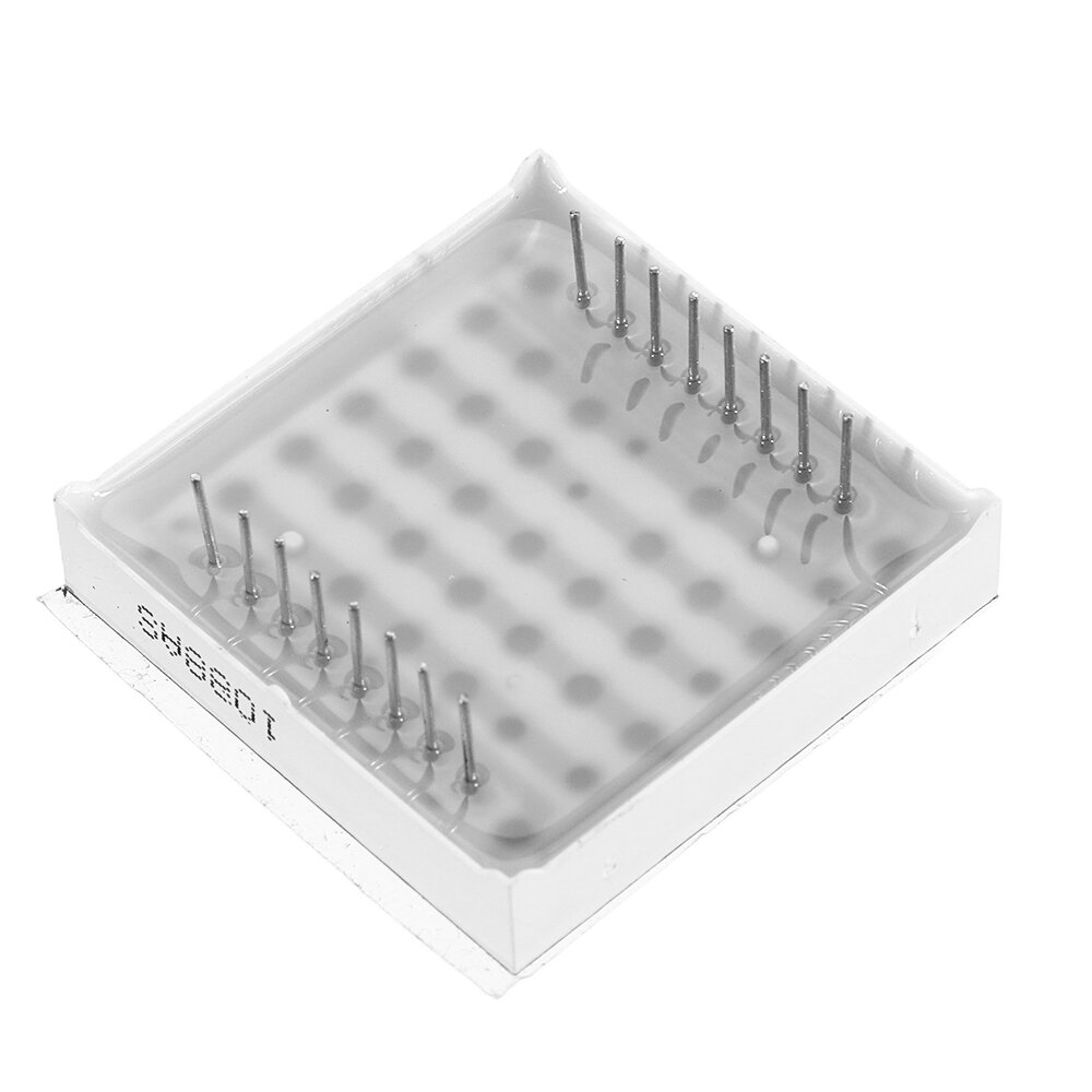
Description:
u00b7 A single module can drive an 8*8 common negative lattice
u00b7 Module operating voltage: 5V
u00b7 Module size: 3.2 cm long, 3.2 cm wide and 1.5 cm high
u00b7 With 4 fixed screw holes and 3 mm diameter, it can be fixed with M3 copper column.
u00b7 Modules with input and output interfaces support multiple modules cascade
Wiring instructions:
The left side of the module is the input port, and the right side is the output port.
When controlling a single module, you only need to connect the input port to the CPU.
When multiple modules are cascaded, the input end of the first module connects to the CPU, the output end connects to the input end of the second module, the output end of the second module connects to the input end of the third module, and so on.
Take 51 single chip computer as an example:
u00b7 VCC 5V
u00b7 GND GND
u00b7 DIN_P20
u00b7 CS_P21
u00b7 CLK_P22
Package included:
5 x MAX7219 Dot Matrix Module DIY kit
Products related to this item
Loading related products...
❮
❯
Videos for similar product
Loading product videos...
❮
❯
Electronics Ranking


- 0 Liked Fi kun si ọkọ
- ATMEGA328 328p 16MHz Pro Mini PCB Module Board 5V
- 216
- $1.97/ $17.070
- 0 Liked Fi kun si ọkọ
- 3Pcs UNO R3 Sensor Shield V5 Expansion Board
- 206
- $3.50/ $10.970